Multi-Gig Automotive Ethernet is the family of Ethernet physical layers that carry more than one gigabit per second — today from 2.5 Gb/s up to 100 Gb/s — over the lightweight cabling and in the harsh electrical environment of a car. It is the data backbone that makes advanced driver assistance, automated driving and software-defined vehicles possible, and it is the technology the NAV Alliance was founded to advance.
Key takeaways
- Multi-Gig means Ethernet faster than 1 Gb/s: 2.5, 5 and 10 Gb/s (IEEE 802.3ch) and 25, 50 and 100 Gb/s (IEEE 802.3cy) over a single shielded pair, plus optical variants (IEEE 802.3cz).
- It replaces a patchwork of proprietary links with one switched, secure and manageable network.
- Cameras, sensor fusion, central compute, storage and zonal backbones are the main drivers.
- The hard problems are physical: EMC, temperature, cable weight, power and lifetime — which is why automotive PHYs differ from data-center Ethernet.
From CAN to the data-center on wheels
For decades, vehicle electronics communicated over low-speed buses. CAN, introduced in the 1980s, carries up to 1 Mb/s (and a few Mb/s with CAN FD); LIN serves simple actuators at 20 kb/s; FlexRay reaches 10 Mb/s for chassis control; MOST was used for infotainment. These buses were designed for short control messages between dozens of electronic control units (ECUs), each owning one function.
Driver assistance and automated driving changed the scale of the problem. A modern sensor suite can include eight to twelve cameras, five or more radars, one or more lidars and ultrasonic sensors, all feeding powerful AI computers that must fuse their data within milliseconds. Add high-definition maps, in-cabin displays, logging for validation and over-the-air updates, and the vehicle becomes what the NAV Alliance calls a data-center on wheels. A single 8-megapixel camera running at 30 frames per second with 12-bit raw output already generates about 3 Gb/s — more than the total capacity of every CAN bus in the car combined, by three orders of magnitude.
Ethernet entered the car first at 100 Mb/s (100BASE-T1, standardized in IEEE 802.3bw in 2015) for infotainment and diagnostics, then at 1 Gb/s (1000BASE-T1, IEEE 802.3bp, 2016). Multi-Gig is the next step: bringing Ethernet to the bandwidth class of the sensors and computers themselves.
The Multi-Gig standards at a glance
| Standard | PHY names | Approved | Medium | Notes |
|---|---|---|---|---|
| IEEE 802.3ch | 2.5GBASE-T1, 5GBASE-T1, 10GBASE-T1 | 2020 | Single shielded differential pair, up to 15 m, up to 4 inline connectors | First Multi-Gig automotive standard; optional EEE and PoDL support |
| IEEE 802.3cy | 25GBASE-T1, 50GBASE-T1, 100GBASE-T1 | 2023 | Single shielded pair (shorter reach at highest rates) | Backbones and central compute; see our 802.3cy deep-dive |
| IEEE 802.3cz | 2.5GBASE-AU … 50GBASE-AU | 2023 | Multimode glass optical fibre | Immune to electromagnetic interference |
| IEEE P802.3dm | Asymmetrical electrical PHYs | In development | Single pair / coax | High-speed uplink from cameras and sensors, low-rate back channel |
All of these are amendments to IEEE 802.3, the Ethernet standard. The automotive physical layers share the same MAC, frame format and higher-layer protocols as office and data-center Ethernet, which is precisely why Ethernet is attractive: the car can reuse a vast ecosystem of switches, software stacks, security protocols and tools.
Why “single pair” matters
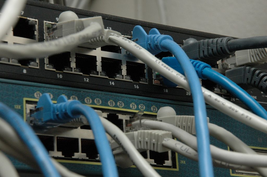
Office Ethernet at 10 Gb/s (10GBASE-T) uses four twisted pairs and a bulky RJ45 connector. In a car, every wire adds weight, cost and assembly effort — the wiring harness is already among the three heaviest and most expensive subsystems of a vehicle. Automotive PHYs therefore transmit full-duplex over a single pair of conductors: one shielded twisted or parallel pair, or for some designs a coaxial cable. Achieving 10 Gb/s or more over one pair requires sophisticated signal processing — multi-level modulation, echo cancellation, adaptive equalization and strong forward error correction (FEC) — all implemented in a PHY that must also meet automotive power, temperature and reliability targets.
What makes automotive Ethernet different from data-center Ethernet?
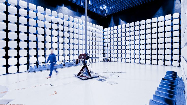
- Electromagnetic compatibility. The link must not disturb the radio receivers in the car (emissions) and must keep working next to electric motors, ignition systems, inverters and phone transmitters (immunity and RF ingress). Read more in our article on Multi-Gig EMC.
- Temperature and vibration. Components typically qualify to AEC-Q100 Grade 2 (−40 °C to +105 °C) or better, and connectors must survive years of vibration and humidity.
- Lifetime. Vehicles stay on the road for fifteen years or more; the link must keep margin as cables and connectors age.
- Fast link-up and low power. Links must come up within milliseconds after wake-up and sleep when not needed — see PoDL, EEE and sleep/wake.
- Functional safety and security. Network elements contribute to ISO 26262 safety goals and must be protected against cyber-attacks — see automotive Ethernet security.
Where Multi-Gig links are used
Sensor links
Cameras, imaging radars and lidars produce the largest data streams in the vehicle. Their traffic is mostly one-way, which is why the NAV Alliance promotes Asymmetrical Ethernet for the sensor interface. Use our camera bandwidth calculator to see which speed a given sensor needs.
Backbone and zonal links
In a zonal architecture, zone controllers collect data from the devices in one region of the car and forward it to central computers. The links between them carry aggregated traffic from many sources and typically need 10 Gb/s today and 25 Gb/s or more for upcoming platforms.
Compute interconnect and storage
Redundant AI computers exchange fused object lists and raw sensor data; data loggers record petabytes of drive data during development; event data recorders and over-the-air update storage all benefit from Multi-Gig connections.
Displays and infotainment
Large cockpit displays and rear-seat entertainment add further video streams, often in parallel with the safety-relevant sensor network.
Inside a Multi-Gig PHY
A Multi-Gig automotive PHY converts frames from the Ethernet MAC into a waveform suitable for the channel. The key building blocks are:
- Line coding and modulation — for example PAM4 (four amplitude levels, two bits per symbol) to keep the signal bandwidth manageable.
- Forward error correction — Reed-Solomon codes correct bursts of errors caused by noise and RF ingress, so the link can run at very low frame-loss rates.
- Echo cancellation — because both directions share one pair, the PHY must subtract its own transmitted signal from what it receives.
- Adaptive equalization — digital filters compensate for frequency-dependent cable loss and reflections from connectors.
- Diagnostics — signal quality indicators and cable tests that let the vehicle detect a degrading link before it fails.
Design challenges the industry is solving
The NAV Alliance working groups focus precisely on the hard problems: defining channels and EMC limits for 25G and 50G PHYs (TWG1/TWG2), integrating Multi-Gig PHYs into ECUs with the right power supply and PCB design rules (TWG3), encapsulating legacy protocols such as I2C, SPI and camera interfaces into Ethernet (TWG4), and defining management, diagnosis and wake-up for the in-vehicle network (TWG5). See the working groups page for details.
Multi-Gig versus SerDes
Many cameras and displays today use proprietary point-to-point serializer/deserializer (SerDes) links, and standardized SerDes such as MIPI A-PHY and ASA Motion Link also exist. SerDes links are efficient for one job — moving video from A to B — but they create islands that require bridging chips and cannot be switched, replicated or secured like the rest of the network. Ethernet brings switching, standard security (MACsec), time synchronization (gPTP) and a single diagnostic and management model to every link. Asymmetrical Ethernet aims to combine the efficiency of SerDes with these network advantages.
What comes next
- Broad production deployment of 10GBASE-T1 in zonal backbones and compute interconnects.
- First 25G and 50G links for central compute and high-resolution sensor aggregation.
- Asymmetrical Ethernet for cameras and sensors as IEEE P802.3dm moves through ballot.
- Deterministic, TSN-based networks using the IEEE 802.1DG automotive profile.
- More integrated switches with security, routing and diagnostics in a single chip.
Frequently asked questions
Is Multi-Gig Automotive Ethernet the same as 10GBASE-T?
No. 10GBASE-T uses four pairs and is designed for buildings. 10GBASE-T1 transmits 10 Gb/s over a single automotive pair with very different EMC and temperature requirements.
How long can a Multi-Gig automotive link be?
IEEE 802.3ch targets link segments up to 15 metres with up to four inline connectors — enough to span any passenger car. Higher-rate PHYs may support shorter reaches depending on the cable.
Does Multi-Gig Ethernet replace CAN?
Not entirely. CAN, CAN XL and 10BASE-T1S remain efficient for low-speed control at the network edge. Multi-Gig links form the high-bandwidth backbone and sensor connections above them.
How can my company get involved?
Join the NAV Alliance as a Promoter, Contributor or Adopter — compare membership levels.
Updated November 2026. Standard numbers and approval years refer to IEEE 802.3 amendments; consult the official IEEE documents for normative requirements.