Few environments are as electromagnetically hostile as a modern car. Electric drive inverters switch hundreds of amperes in nanoseconds; DC-DC converters, ignition systems and wireless chargers radiate; and the car itself carries sensitive radio receivers for AM/FM, DAB, GNSS, cellular and Wi-Fi. A Multi-Gig Ethernet link must neither disturb those receivers nor be disturbed by everything around it. That is the discipline of electromagnetic compatibility (EMC) — and it is one of the main reasons NAV Alliance working groups specify EMC requirements alongside PHY speeds.
Key takeaways
- EMC has two halves: emissions (what the link radiates) and immunity (how it tolerates disturbance, including RF ingress).
- Higher data rates spread energy to higher frequencies, raising both emission risk and sensitivity.
- Balance and mode conversion of the channel are as important as shielding.
- Tests include CISPR 25 emissions, bulk current injection, stripline and direct power injection — plus vehicle-level validation.
- NAV Alliance TWG1/TWG2 defined RF-ingress characterization and limit lines at PHY inputs for 25G/50G links.
Emissions: staying quiet
A differential signal on a perfectly balanced pair produces fields that largely cancel. In practice, small imbalances in the cable, connectors, PCB traces or PHY output convert part of the differential signal into common-mode current, which radiates efficiently from the cable acting as an antenna. Automotive emission limits are strict because the receivers they protect operate at very low signal levels. CISPR 25, the international standard for vehicle component emissions, defines measurement methods and limit classes for conducted and radiated emissions across the bands used by vehicle receivers.
Design measures to reduce emissions include:
- shielded cables and connectors with low-impedance 360° shield termination;
- tightly controlled balance in cable manufacturing and connector design (low mode conversion);
- common-mode chokes and careful filtering in the MDI circuit;
- PHY transmit spectra shaped to minimize energy in sensitive bands;
- PCB layout with continuous reference planes and symmetric differential routing.
Immunity and RF ingress: staying robust
Immunity is the ability to operate correctly in the presence of disturbances. For Ethernet links the critical mechanism is RF ingress: external fields induce common-mode currents on the cable shield or conductors; any imbalance converts part of this into differential noise at the receiver. At Multi-Gig speeds the receiver’s eye opening is small — with PAM4, each level is a third of the swing — so the tolerable noise is limited. Robust links rely on:
- good shielding effectiveness and coupling attenuation of the cable and connectors;
- high common-mode rejection in the PHY receiver;
- forward error correction sized for burst errors;
- fast adaptation and retraining strategies that maintain the link during transients.
The NAV Alliance TWG1/TWG2 charter included characterizing and measuring the RF ingress over target channels (cables, connectors, module) and defining limit lines for RF ingress levels at PHY inputs for 25G and 50G links. Such limit lines bridge two worlds: they tell PHY designers what disturbance the receiver must survive and tell harness suppliers how much the channel may let through.
Why EMC gets harder at higher speed
| Factor | Effect of higher data rate |
|---|---|
| Signal bandwidth | Extends into hundreds of MHz to several GHz, overlapping more radio services |
| Cable and connector behaviour | Imbalances and shield transfer impedance matter at higher frequencies |
| Receiver noise margin | Smaller eye openings, more sensitive to residual differential noise |
| PCB effects | Via stubs, reference-plane gaps and connector footprints become significant |
Common test methods
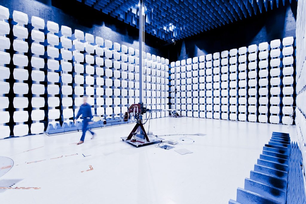
- CISPR 25 — conducted and radiated emission measurements of components and modules in a shielded (anechoic) chamber.
- Bulk current injection (BCI, ISO 11452-4) — RF current is injected onto the harness with a clamp to simulate coupling from nearby fields.
- Radiated immunity (ISO 11452-2) — the device under test is exposed to strong RF fields from an antenna.
- Stripline and TEM cell tests — controlled field coupling into cables for repeatable channel characterization.
- Direct power injection (IEC 62132-4) — RF injected at IC pins to characterize PHY immunity at chip level.
- Transient tests (ISO 7637) — fast electrical transients on supply and signal lines.
Component-level tests are complemented by vehicle-level validation, because harness routing and grounding in the real car determine the final coupling.
Design checklist for Multi-Gig EMC
- Choose cable and connector systems specified for the target data rate with documented coupling attenuation and mode-conversion performance.
- Follow the PHY vendor’s MDI reference design, including common-mode termination and ESD protection placement.
- Route differential pairs symmetrically with matched lengths and minimal via transitions; keep a solid reference plane.
- Terminate shields 360° at the connector and the housing; avoid pigtails.
- Separate high-speed harness bundles from high-power cables, especially in electric vehicles.
- Verify early with near-field scans and pre-compliance tests before formal CISPR 25 measurements.
- Monitor link-quality indicators (such as SQI) during immunity tests to measure remaining margin, not just pass/fail.
Electric vehicles raise the bar
High-voltage inverters, on-board chargers and DC-DC converters generate strong broadband disturbances, and their cables run close to data harnesses. EV platforms often impose tighter internal limits than the baseline standards. Optical links (IEEE 802.3cz) are one option where electrical immunity margins are hard to achieve; careful harness separation and shielding are the other.
Frequently asked questions
Is shielding always required for Multi-Gig links?
For 2.5 Gb/s and above, shielded pairs or coax are typical in automotive designs. Unshielded operation is common at 100 Mb/s and 1 Gb/s.
What is mode conversion?
The conversion between differential and common-mode signals caused by imbalance. Low mode conversion means lower emissions and better immunity.
Who defines the EMC limits for my product?
Standards such as CISPR 25 define methods and classes; each OEM specifies the limits and test levels in its component requirements.
Updated November 2026.