At 100 Mb/s almost any twisted pair works. At 10 Gb/s and beyond, the channel — cable, connectors, PCB traces and everything in between — decides whether a link has margin for fifteen years on the road or fails on a cold morning. This guide explains the key channel parameters, the cable and connector types used for Multi-Gig automotive Ethernet, and practical harness design tips.
Key takeaways
- A channel is specified by insertion loss, return loss, crosstalk, mode conversion and shielding/coupling attenuation over frequency.
- Multi-Gig automotive links use shielded parallel or twisted pairs and, in some designs, coaxial cable.
- Inline connectors are the biggest source of reflections; their number and quality limit reach.
- Ageing, temperature and humidity change cable behaviour — design with margin.
What “the channel” means
In IEEE terms, the link segment is the cabling between the two MDI connectors of the communicating devices, including inline connectors. The full channel seen by a PHY also includes the PCB traces, common-mode chokes, ESD protection and connector footprint between the PHY pins and the MDI — sometimes called the MDI-to-PHY channel. NAV Alliance TWG1/TWG2 defined specifications for both portions for 25G and 50G links, because at these speeds the PCB can consume a significant part of the loss budget.
Key parameters
| Parameter | What it describes | Why it matters at Multi-Gig |
|---|---|---|
| Insertion loss (IL) | Signal attenuation versus frequency | Rises with frequency and length; sets maximum reach |
| Return loss (RL) | Energy reflected by impedance mismatches | Reflections appear as echo the PHY must cancel |
| Micro-reflections | Small periodic impedance variations along the cable | Can create narrow notches in the channel response |
| Crosstalk / alien crosstalk | Coupling between neighbouring pairs or cables | Adds noise that cannot be cancelled |
| Mode conversion (LCL/LCTL) | Differential ↔ common-mode conversion | Drives emissions and susceptibility |
| Coupling attenuation / screening | Shield effectiveness | Protects against RF ingress and limits emissions |
Cable types
Shielded parallel pair (SPP) and shielded twisted pair (STP)
Two insulated conductors under a common foil and/or braid shield. Parallel pairs (not twisted) can offer very consistent impedance and low skew at high frequency; twisted versions add some intrinsic balance. These cables are the natural medium for single-pair Ethernet PHYs such as 10GBASE-T1 and 25GBASE-T1.
Coaxial cable
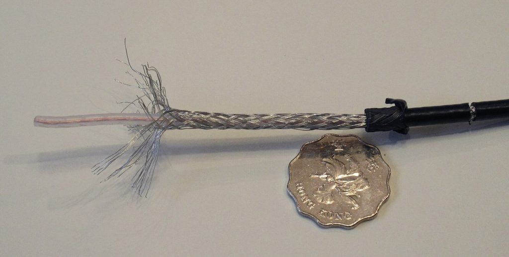
A single centre conductor surrounded by dielectric and a braided shield, as shown in our article image. Coax is widely used for camera SerDes links and supports power over coax. It is a single-ended medium, so PHYs designed for differential pairs require adaptation; some automotive Ethernet and asymmetric solutions support coax operation.
Optical fibre
For the highest immunity, IEEE 802.3cz specifies multimode glass optical fibre at 2.5 to 50 Gb/s — no electrical coupling at all, at the cost of optical connector handling.
Connectors
Automotive high-speed connector families — for example Rosenberger’s H-MTD® (differential) and HFM® (coaxial) systems, along with comparable families from other suppliers — are designed for controlled impedance, 360° shielding, mechanical robustness and automated harness assembly. Every inline connector, however, introduces a small impedance discontinuity and therefore a reflection. Standards define channels with a maximum number of inline connectors (IEEE 802.3ch specifies up to four in a 15 m link segment). At 25 and 50 Gb/s, connector quality, the number of inline connections and their spacing become critical design choices.
Environmental effects and ageing
- Temperature: insertion loss increases with temperature; a channel that passes at 23 °C may lack margin at 105 °C.
- Humidity: moisture ingress into the dielectric can raise loss over time; jacket materials and sealing matter.
- Mechanical stress: tight bends, crushing and vibration change geometry and impedance; respect minimum bend radii.
- Connector wear: mating cycles and fretting corrosion affect contact resistance and shielding.
Specifications therefore define requirements over temperature and after ageing, and designers keep margin for the vehicle’s lifetime.
PCB and MDI design
From the PHY pins to the connector, keep differential pairs symmetric and short, minimize vias and remove via stubs, maintain a continuous reference plane, and follow the PHY vendor’s reference design for common-mode chokes, termination and ESD protection. NAV Alliance TWG3 addresses PCB design rules, additional components and diagnosis for Multi-Gig PHY integration in ECUs and vehicle computers.
Power over the same cable
Cameras and some sensors receive power over the data cable — Power over Data Lines (IEEE 802.3bu) on pairs or power over coax. The coupling network (inductors and capacitors) must pass DC while being invisible at signal frequencies; its parasitics enter the channel budget. See PoDL and Energy-Efficient Ethernet.
Harness design tips
- Choose the cable and connector system for the highest data rate you expect over the platform life, not just today’s.
- Minimize the number of inline connectors on Multi-Gig links; place necessary ones thoughtfully.
- Keep high-speed bundles away from high-voltage and high-current cables.
- Specify and verify channel parameters with vector network analyzer measurements on production-representative harnesses.
- Use the PHY’s built-in diagnostics (signal quality indicators, cable tests) in validation and in the field.
Frequently asked questions
Can I reuse 1 Gb/s cabling for 10 Gb/s?
Usually not without verification. Multi-Gig PHYs require channels specified up to much higher frequencies, generally shielded.
Coax or shielded pair?
Both are used. The choice depends on the PHY, power delivery, harness standardization and the OEM’s connector strategy.
How long can the link be?
IEEE 802.3ch targets up to 15 m with four inline connectors; higher-rate links may target shorter reaches. Use our glossary for terms and contact us for design reviews.
Updated November 2026. Connector trade names are trademarks of their respective owners.